Model operations
The user can perform operations on the created CAD model thanks to the btn:[Model operations] drop-down menu or inside the Tools menu. The list of available operations may be subject to changes depending on installed additional modules.
The following operations are always available in EDGE.
Check for overlaps
This operation allows the user to check if there are no overlaps inside the geometry, meaning that there are no shapes overlapping each other.
It is possible to choose if "touching" shapes should be considered as overlapping or not. To launch the calculation, the user can click on the  button. The
  button allows the user to stop the calculation at any time.
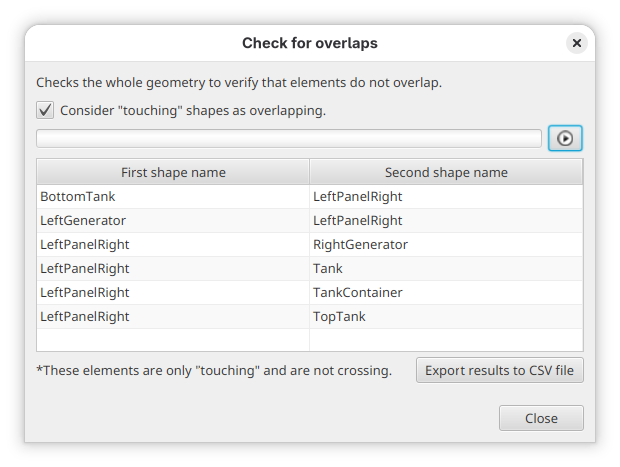
By clicking on the btn:[Export results to CSV file], it is possible to save the list of overlapping shapes to a .csv file.
Compute surface
This operation allows the user to obtain the surface of the various elements of the geometry. The computed value is an approximation of the real surfaces value based on 3D meshing of the shapes.
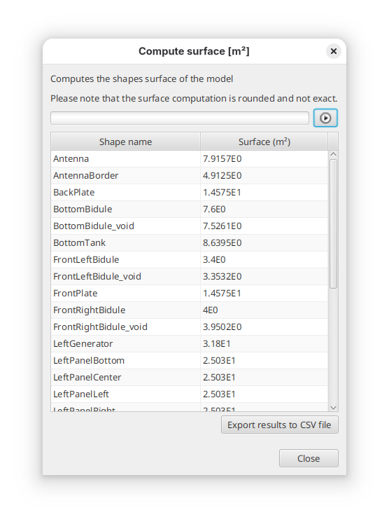
By clicking on the btn:[Export results to CSV file], it is possible to retrieve the computed results to a .csv file.
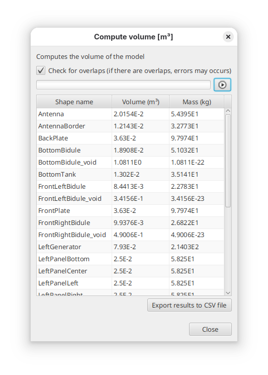
Compute volume
This operation allows the user to obtain the volume of the geometry. The computed value is an approximation of the real volume value based on 3D meshing of the shapes.
Here also, it is possible to retrieve the results into a CSV file.
|
Computation function limited capabilities
Computation of volume (and thus mass) may take quite some time over complex systems. This is an indicative tool to check consistency with real system. Take care with this tool on complex systems. |
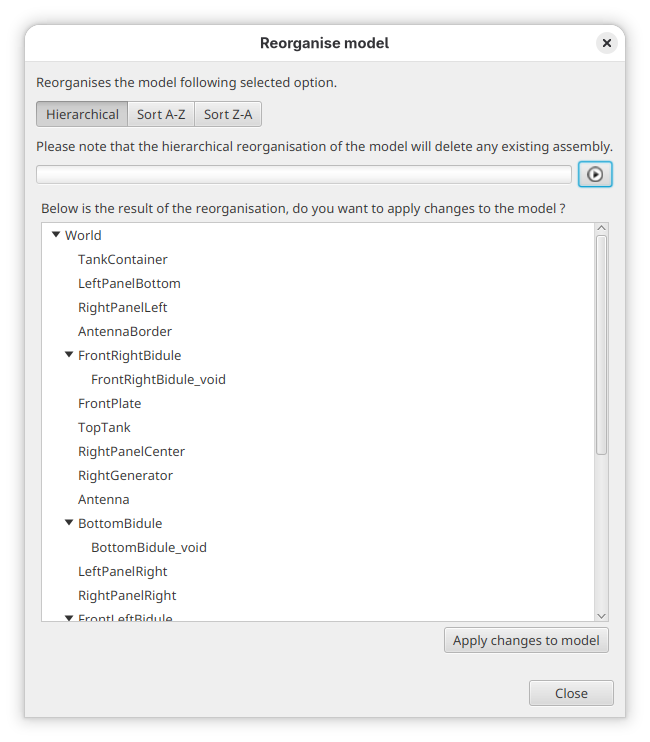
Reorganise model
This operation allows the user to reorganise the model following several options. The tool computes the new hierarchy, displays the results to the user and proposes to modify the model accordingly
- Hierarchical
-
Checks the consistency of the hierarchy of the model. Indeed, to get proper radiations results, elements that are included in other ones (geometrically) should be placed as child of the geometrical shapes they are in. This option computes the real hierarchy.
- Sort A-Z
-
Sorts the children of each element by alphabetical order.
- Sort Z-A
-
Sorts the children of each element by reverse alphabetical order.
|
Removal of logical assemblies
The Hierarchical option will remove all assemblies from the model as they do not have a physical representation that can be used to find the real hierarchy of shapes. As some code may not handle well assemblies, this tool can be used to automatically remove these assemblies. |
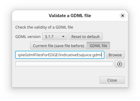
Validate GDML file
This operation checks the syntax validity of a GDML file against the GDML file format specifications. It is possible to check the current file (if saved beforehand) or any file from the system.
It is possible to select the wanted GDML file version used to check the XML validity of the file.