IC Meshing Plugin
|
Access to this plugin is free of charge, the installation procedure is detailed in the Tools menu description. |
Volume Mesh Creation for Internal Charging Analysis, in short Internal Charging Meshing or IC Meshing, is an EDGE plugin developed to widely facilitate the creation of scoring volume mesh used in the SpaceSuite internal charging modelling chain.
First, this modelling chain needs the CAD of the system from a GDML file created, for example, with EDGE. This file is then used by MoORa to compute the interactions between the particles coming from the space environment and the materials.
During this computation, both the deposited dose and charge are scored in a volume mesh used later in the modelling chain as initial condition for SPIS-IC to compute the internal charging effect in the dielectric.
The purpose of the Internal Charging Meshing EDGE plug-in is to compute this volume mesh where both the deposited dose and charge will be computed later by MoORa.
Standing for Modelling Of Radiations, MoORA is a user-friendly and simple to use software developed by Artenum that helps modelling the radiations transport using Geant4, a Monte-Carlo numerical kernel.
Internal Charging Meshing provides tools for GDML manipulation to: select the dielectrics we want to study; move elements relatively to each other and merge common surfaces between elements. Then, an easy-to-use mesh editor generates a volume mesh, which can be anisotropic depending on the user needs.
Internal Charging Meshing starts from a GDML file used for Geant4 analysis. The hierarchy of the GDML geometry must be consistent with the Geant4 requirements. The volume mesh to create will be saved on the disk in a .msh Gmsh mesh file. The volume mesh to create is the input CAD file for the SPIS-IC simulation. It is usually the dielectric we want to study where the surface continuity has to be guaranteed. Finally, the Internal Charging Meshing plug-in creates a MoORa project where the CAD model is the GDML file defined in EDGE, the particle source is a sphere surrounding the geometry, with a cosine-law angle distribution and electrons at \(1MeV\) and both the deposited dose and charge will be computed on the scoring volume mesh.
The plug-in is available from the "model operations" drop down
menu. If users want to create a complete .moora project, the
GDML CAD file needs to be finalized before to use the plugin.
Home
At the launching, the Internal Charging Meshing opens the
Home perspective  of the plug-in a new window,
displaying two icons:
of the plug-in a new window,
displaying two icons:
-
Only available if a geometry is present in EDGE. Choosing this option loads the current GDML geometry, except the world element and goes to the next step.
The hierarchy of the GDML geometry must be consistent with the Geant4 requirements: a shape containing another shape must be the parent of this shape in the data tree model. 
-
Always available, it allows importing previously designed B-Rep geometries. Choosing this option sends directly to the Mesh creation perspective (see Mesh creation).
Imported .geo file cannot be modified inside the application.
Subsystem selection
Subsystem selection perspective ( )
is dedicated to the selection of the GDML subsystem we want to study.
)
is dedicated to the selection of the GDML subsystem we want to study.
Its interface is divided in tree part, as it can be seen below:
-
Left bar: Perspective selector to navigate between the different perspectives;
-
Left: Subsystem selection panel, detailed in the next paragraphs;
-
Right: 3D Viewer provides a 3D view of the complete GDML model.
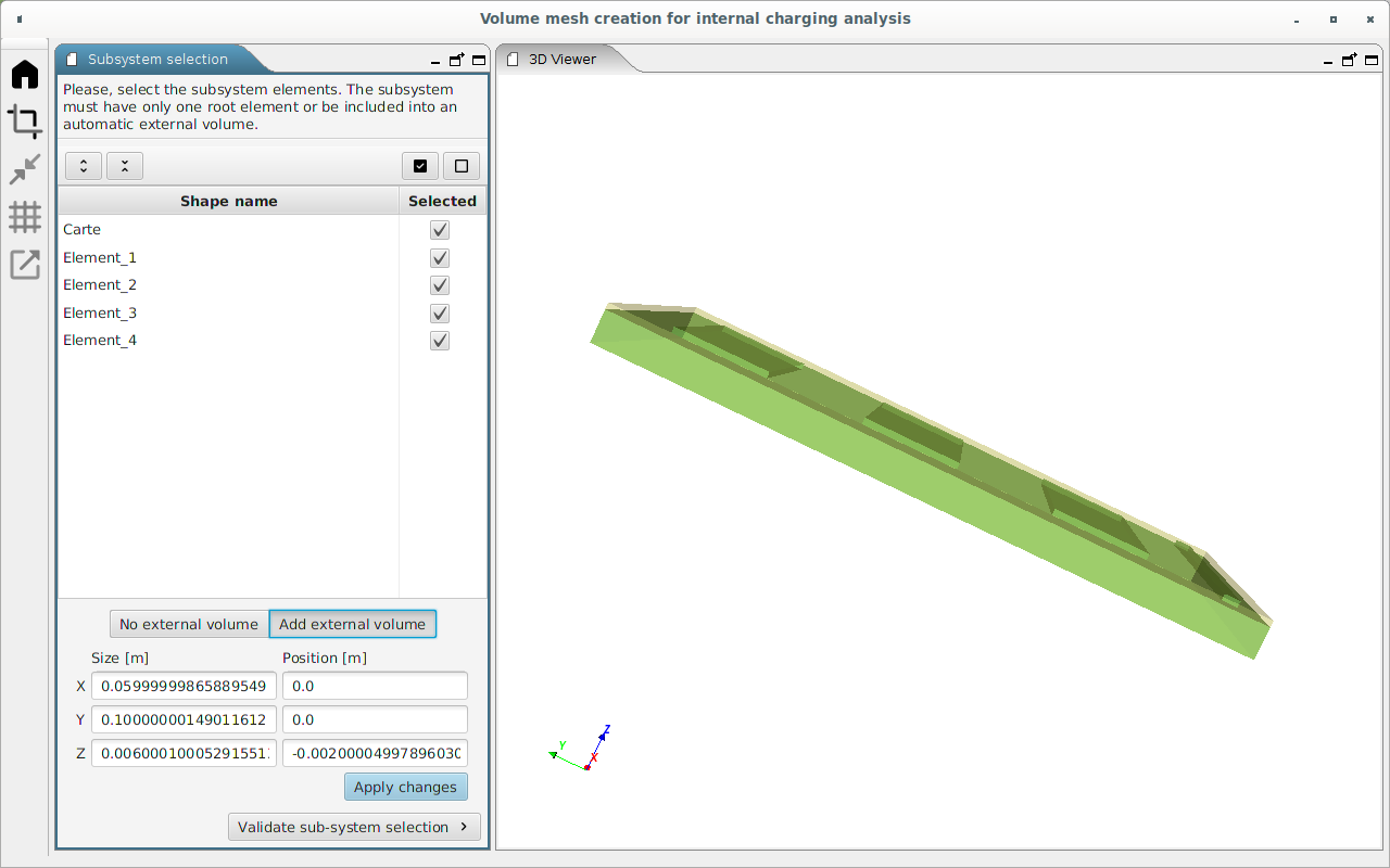
In the subsystem selection interface, all the GDML elements are listed. This list can be expanded  or collapsed
  by clicking on the corresponding icons.
Relevant GDML elements must be selected in the subsystem selection interface. They can be selected or unselected individually. Moreover, click on  to select all the elements, while
  cancels the whole selection. Selected elements are coloured in green inside the 3D viewer.
Users need to select a sub-system with only one parent elements containing all other ones. So, if a single Gdml element is selected, sub-system selection can be directly validated (clicking on btn:[Validate sub-system selection]).
Otherwise, if several elements are selected without a unique
selected parent, the user has to create an external volume
including all the selected shapes (btn:[Add external volume]
button). The shape of the new external created volume is
necessarily a rectangular parallelepiped and can differ from
the world element defined in the standard EDGE interface.
Nevertheless, it has to be included inside the world element
defined in EDGE. The default dimensions of this volume at its
creation are the minimal values to entirely contain the internal
elements. This external shape can be reshaped and repositioned
using the x, y and z size and position fields visible on
figure above. The new shape is
validated by clicking on btn:[Apply changes].
When the external volume is well shaped, the user can pass to the next perspective by clicking on btn:[Validate sub-system selection].
Put solids in contact
The objective of this step is to put in contact shapes with other shapes. It is necessary because the GDML CAD model respects the GEANT4 numerical kernel constraints (especially shapes must not be in contact with other shapes neither overlapping) but in SPIS-IC numerical kernel, constraints regarding the geometry are different: the shapes which are really in contact must also be in contact in the geometry (to allow the charge to move from one shape to another one by conductivity).
This is why, it may be necessary to put shapes from the initial GDML model in contact with other shapes. Depending on the study, this operation is not mandatory.
The Put solids in contact perspective interface
( ) seems quite similar to the
Subsystem selection perspective, as it can be seen below. It
allows to move GDML elements between each other to put them in
contact.
) seems quite similar to the
Subsystem selection perspective, as it can be seen below. It
allows to move GDML elements between each other to put them in
contact.
An element can be selected as:
- A target
-
Single target is defined for each move. It is the motionless reference element of the put in contact.
The selected target is coloured in yellow in the 3D viewer. - Move shape(s)
-
Several move shapes can be defined simultaneously for a move.
Move shape(s) are coloured in green in the 3D viewer.
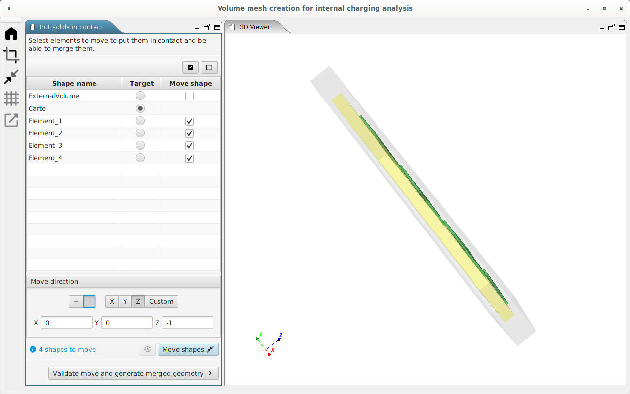
Next, the move direction of the move shape has to be defined.
Two ways can be used to choose this direction:
-
The quick definition icons btn:[+] / btn:[-] and btn:[X] / btn:[Y] / btn:[Z] allow to define a move direction parallel to one of the director vectors of the 3D geometry.
The selected direction is displayed in the field below.
-
Alternatively, the move direction can be defined freely in the input fields by selecting on btn:[Custom] or by directly editing the content of X/Y/Z fields.
When the target, move shapes and direction motion are correctly
defined, the modification can be applied by clicking on the
btn:[Move shapes] button . Previous motions can be canceled with
the  button to go back to the initial state.
|
Limiting motion of GDML shapes
If the length of the motion is greater than 1 µm, a warning message is displayed. Indeed, moving the shape is a modification regarding the GDML geometry used by the Geant4 numerical kernel. Move shape with a distance too big will lead to unexpected scoring Geant4 simulation results where the scoring volume mesh and its corresponding GDML shape are in two different positions. This warning will not be displayed for the created external volume because it is an empty volume with no shape defined in the GDML CAD model. |
When all the desired motions have been realised, click on btn:[Validate move and generate merged geometry] to go to the next perspective.
| The put in contact tool is actually not able to merge the edges from different GDML elements. |
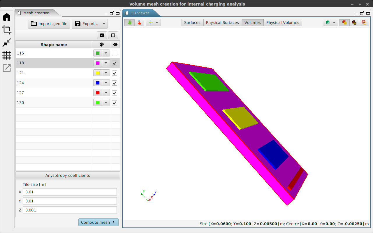
Mesh creation
The Mesh creation perspective  provides a tool to generate a Gmsh mesh. This mesh may be computed
with strong anisotropy if necessary.
provides a tool to generate a Gmsh mesh. This mesh may be computed
with strong anisotropy if necessary.
For the study of the effect of internal charging, the volume mesh on the dielectrics will be used to score both the deposited dose and charge rates with Monte-Carlo simulations. Ideally, the volume mesh would have small tetrahedra in all directions to have a good modelling of the internal charging effects. Nevertheless, the CPU time of the Monte-Carlo simulations can be long to reach a good statistic in all of these tetrahedra. The objective is to reach a good ratio between the size of the tetrahedra and the CPU time which will keep internal charging results accurate enough. The smallest the number of tetrahedra in the volume mesh is, the shortest the CPU time will be.
To minimize the number of tetrahedra in the volume mesh of the dielectric one solution is to have small tetrahedron size in the direction where the electric field and potential will change quickly and bigger tetrahedron size in other directions. In some situations, like high voltage dielectric card for example, strong anisotropic volume mesh needs to be computed.
Mesh can be generated from:
-
the GDML subsystem designed in the chain detailed in the two previous sections. The generated geometry is a Gmsh .geo file. Both surfaces in contact and volume with other volume inside it have been "smartly" computed by creating surfaces and volumes with holes to be consistent with the SPIS-IC numerical kernel constraints regarding the geometry;
-
an external
.geofile loaded by clicking on the btn:[ Import .geo file] icon.
btn:[Export …] icon enables to export the geometry to a Gmsh .geo v2 or v4 file.
The mesh element size is governed from the X/Y/Z anisotropy coefficients fields, where the tile size is written in meters.
In order to generate a mesh with a sufficient resolution, an anisotropy coefficient size have to be a fraction of the sensitive element size following the concerned direction. If an anisotropy coefficient size is greater than the dimension of a shape, this shape will be mesh with the coarsest possible cells.
To facilitate the choice of Anisotropy coefficient size, the 3D viewer of the mesh creation perspective presents several functionalities.
| Button | Action |
|---|---|
|
allows moving and turn the viewer |
|
allows to select a shape of the geometry in the 3D viewer. The shape is highlighted in the list. |
|
drop-down menu regrouping the same icons as EDGE to align the 3D view with the X/Y/Z axis |
|
drop-down menu that allows to choose the transparency of all the surfaces |
|
displays the surface of the shapes |
|
displays the surface of the shape and the edge of the mesh |
|
displays only the mesh edges |
Surfaces |
displays all the surfaces of the geometry in the shape list |
Physical Surfaces |
displays in the shape list the Gmsh physical surfaces where specific properties will be applied in SPIS-IC |
Volumes |
displays the volume of the geometry ranked by their id number in the shape list |
Physical Volumes |
displays in the shape list the physical volume of the geometry ranked by their name where will be applied in SPIS-IC specific properties (for example the material properties) |


In the shape list on the left side of the perspective, each item can be selected or unselected which will change the visibility of the shape in the 3D view and will not impact the mesh creation.
Moreover, selecting a shape displays this dimension in the bottom of the 3D viewer. That can be helpful to correctly choose the anisotropy coefficients.
By clicking on the colour box of each item, the colour shape of the selected item will be changed in the 3D view according to the new selected colour.
When the field are correctly filled out, the mesh can be created by clicking on btn:[Compute mesh].
Mesh checking and export
The last perspective  , which can
be seen below, allows to check and export the GDML subsystem
and the Gmsh mesh to a MoORa Project.
, which can
be seen below, allows to check and export the GDML subsystem
and the Gmsh mesh to a MoORa Project.
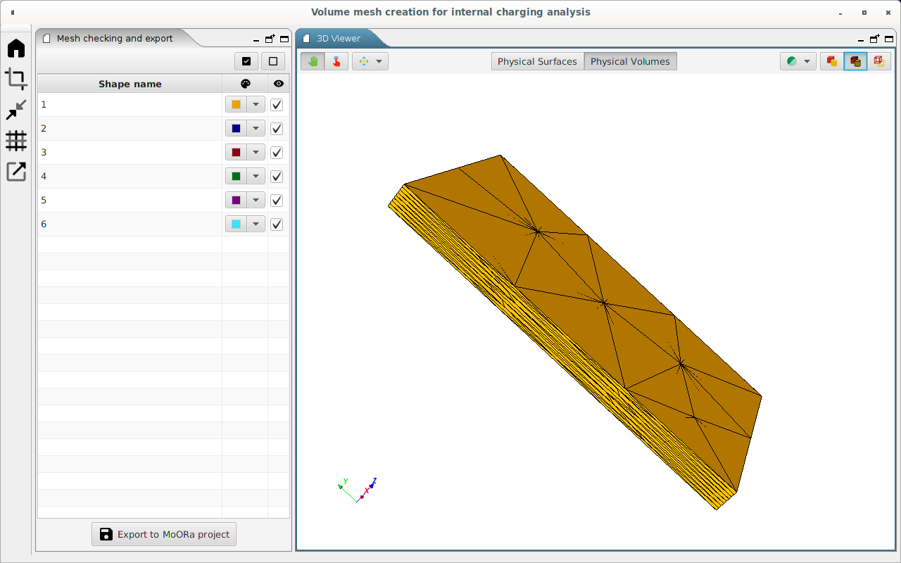
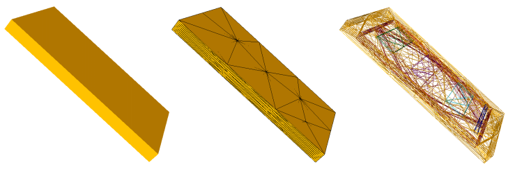
The 3D viewer interface of this perspective is very similar to the previous one. It allows checking visually the mesh by modifying the 3D viewer option as it can be seen below.
When the check is complete the geometry and the mesh can be export
by clicking on btn:[Export to MoORa project], or the
mesh can still be modified by returning to the previous perspective
.