Geometry edition
The Geometry perspective is the main perspective of EDGE since it allows the creation and the edition of geometrical elements.
Geometry perspective
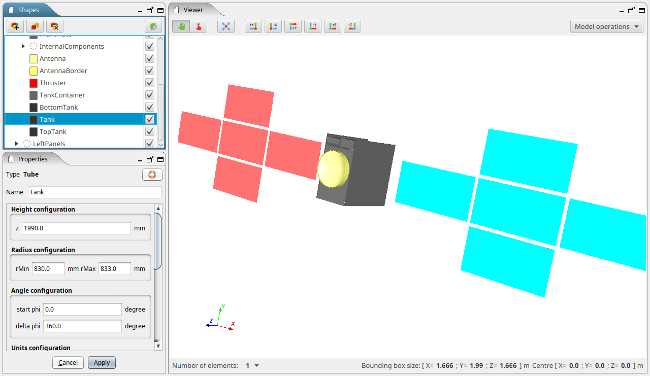
It is the main perspective of EDGE displayed by default at the launching. It has three main panels to edit the geometry, as shown below.
-
Top left: Shapes Tree panel, to visualise and edit the list of geometric shapes;
-
Bottom left: Properties panel, to edit the properties of the currently selected shape;
-
Right: 3D Viewer panel provides a 3D view of the modelled system.
These panels, as well as the 3D View panel, can be moved, detached or maximized at the user’s liking using the buttons on their top right corner.
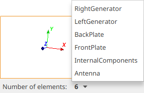
Shapes tree
The Shapes tree lists all the shapes currently defined in the geometrical model and displayed in the 3D scene.
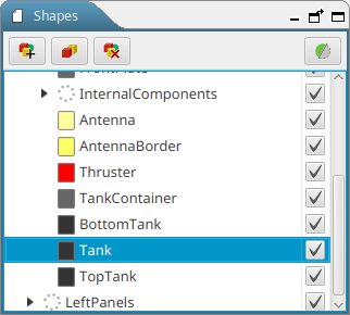
It also shows the hierarchy of the shapes.The shape(s) currently selected is (are) highlighted in the 3D view on the right with a red box.
It is also possible to move one geometry element and all its children elements to another logical location in the geometry tree.This feature is available only when the "enable drag’n’drop" preference has been enabled in the preferences.
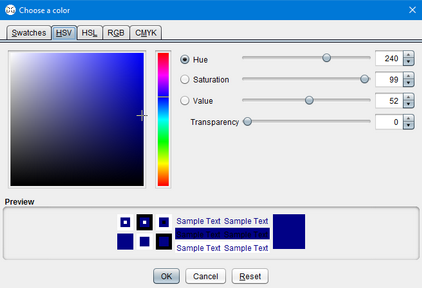
On the left of each shape’s name, a click on the coloured box opens a dialog that allows changing the colour of the shape in the 3D view. It is also possible to change the transparency of the selected element in this dialog box, as shown below.
Additionally, a checkbox on the right of the shape name controls the visibility of the object in the 3D view. When changing the visibility on an assembly with this checkbox, all its children shapes visibility is changed accordingly.
On top of the tree, buttons are used to control the shapes. Availability of buttons depends on the current selection of elements.
| Button | Action | Available |
|---|---|---|
|
Opens a dialog box to add a new shape to the tree, if one shape is selected, the new created shape will be added as children of the selected shape. If none selected, the new element will be set at the world element if the geometry is empty or as children of the existing world element if present. |
Zero or one shape selected |
|
Creates Boolean operation using selected shapes |
At least 2 shape selected |
|
Duplicates the selected shape(s) |
At least 1 shape selected |
|
Deletes all the shapes currently selected in the tree |
At least 1 shape selected |
|
Offers the possibility to use a clipping filter |
Exactly 1 shape selected |


Clipping tool
The clipping button triggers the apparition of a dialog box allowing the user to set the parameters of the clipping filter, as shown below.It performs a visual cut in the geometry to view more precisely the inner geometry of the modelled system.
The clipping is set with the coordinates of a centre point and a normal direction.It will keep the geometric representation of the selected element in the half-space defined by this point and the normal.
To get a more interactive setting, you can select the btn:[Display 3D control widget] option that will display an interactive control in the 3D view to change the clipping.These 3D controls of the filter are materialised by a sphere (representing the centre of the clipping operation) and an axis with two arrows (representing the normal direction).
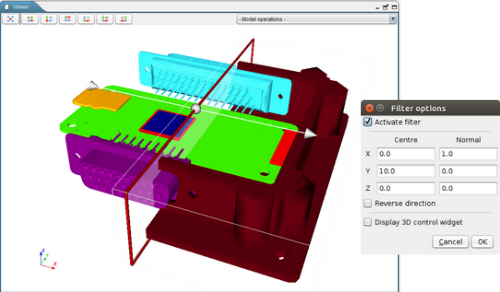
| The clipping filter is just a visualisation tool, it will not change the geometry definition. |
Properties panel
This panel shows the properties of the shape currently selected in the Shapes tree. It shows shape intrinsic properties only if there is one — and only one — shape selected. Depending on the shape selected, the properties displayed change accordingly (not the same parameters for a box and a sphere, for example). If several shapes are selected simultaneously, the properties panel will only display position / orientation setup.
Shape properties
The user can thus define the dimensions of the shape. For each shape, parameters vary and explanatory schemes are presented in the Supported shapes schematics annex. These pictures are also available in the software by clicking on the  button.
Units selection
This panel shows also fields to choose the position and orientation of the object and the unit of measure. The unit for parameters, positions and rotations can be changed and an automatic conversion of values is proposed. The default units are millimetres (mm) for lengths and radians (rad) for angles, but it can be changed in the preferences.
Position and orientation
The orientation parameter represents the orientation of the shape around its centre of mass: each angle (also known as Euler angle) represents an orientation around the X, Y and Z axis respectively.
| Those rotations are applied in the following order: first the Z orientation, then the Y one and finally the X rotation. Then, and only then, the translation is applied. |
Setting position and orientation for several shapes
When several shapes are selected inside the tree, the properties panel will enable to change the position and orientation of all the shapes with the panel below.
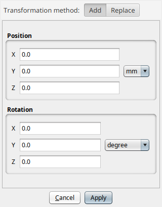
This panel allows setting the translation and rotation to apply to the elements. These transformations can replace the current position and orientation properties of the objects or be added to any existing placement information.
For example, for an object at a (1, 1, 1) position, a transformation of (2, 0, 0) with btn:[Add] selected will move the object to (3, 1, 1), when selecting btn:[Replace] will move it to (2, 0, 0).
3D Viewer
The 3D Viewer is showing in real-time the product of the GDML model.
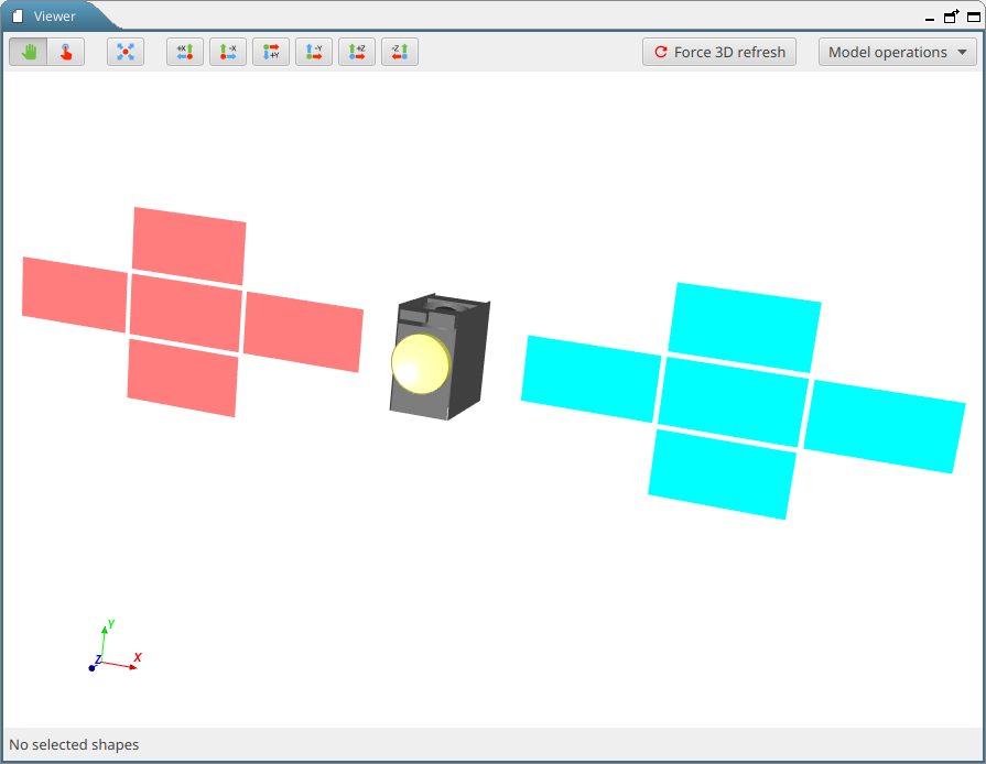
It is possible to interact with the view using the mouse to control it:
| Action | |
|---|---|
Left click |
(hold) and movement: rotate the scene |
Wheel |
(hold) and movement: translate the scene |
Right click |
(hold) and movement: zoom |
Or, with the keyboard:
| Key | Action |
|---|---|
kbd:[R] |
Resets the view and shows all the shapes of the scene |
kbd:[I] |
to zoom In |
kbd:[O] |
to zoom Out |
kbd:[W] |
displays the shapes as Wireframes |
kbd:[S] |
displays the shapes as Solid |
The up/down/left/right arrows rotate the scene.
The buttons at the top of the view also facilitate its handling (from left to right):
| Button | Action |
|---|---|
|
enables to select whether the mouse should move the scene (button on the left) or pick elements (button on the right), see details below. |
|
resets the view and shows all the shapes of the scene ("R" key shortcut) |
|
aligns the view along +X axis |
|
aligns the view along -X axis |
|
aligns the view along +Y axis |
|
aligns the view along -Y axis |
|
aligns the view along +Z axis |
|
aligns the view along -Z axis |
|
forces the refresh of the 3D view (recomputes the visualisation of all elements) |


By default, as presented earlier, the mouse enables to move, pan and zoom inside the 3D view of the system. By clicking on the Pick button presented in the table above, hovering the mouse over the 3D viewer will focus the various elements of the scene, clicking with the mouse will select the shape and move back to interaction mode.
On the top left of the 3D view, a drop-down menu allows the user to choose a model operation to perform.
On the bottom of the 3D view, an information bar displays useful information about the current selection: the number of selected elements as well as the size and the position of the bounding box — the red box around selected elements. It is possible to click on the number of selected shapes to display a list of the currently selected shapes.
Available geometric shapes
EDGE handles several primitive geometric shapes as shown below. Other kind of shapes are also supported and presented in next section.
| Available shape | Non-handled shape |
|---|---|
Polycone |
|
Generic Polycone |
|
Polyhedron |
|
Generic Polyhedron |
|
Torus Segment |
|
Tube with Hyperbolic Profile |
|
Cut Tube |
|
Twisted Box |
|
Twisted Trapezoid |
|
Twisted General Trapezoid |
|
Twisted Tube Segment |
|
Extruded Solid |
|
Arbitrary Trapezoid (Arb8) |
Inside EDGE, a ![]() button is available to show detailed schematics presenting the various parameters for each shape.These schematics can also be found in Supported shapes schematics annex
button is available to show detailed schematics presenting the various parameters for each shape.These schematics can also be found in Supported shapes schematics annex
Other available shapes
EDGE is able to handle other types of shapes other than the plain CSG primitives presented in previous section.
Assemblies
In EDGE, the user has the possibility to handle “assembly” elements.Those elements are grouping several shapes without being attached to a geometric shape.
Assemblies are part of the GDML format but may not always be well-supported by numerical kernels.
| It is possible to remove all assemblies from the CAD by using the Reorganise model tool. |
Tessellated Solid
Solids with complex geometries can be constructed by importing tessellated surfaces, including initially B-Rep based models. It is possible to import tessellated shapes by using the import function available in the menu:File[Import] menu or inside the "Add new shape" dialog.
Those tessellated surfaces are converted into an equivalent GDML tessellated solid object.
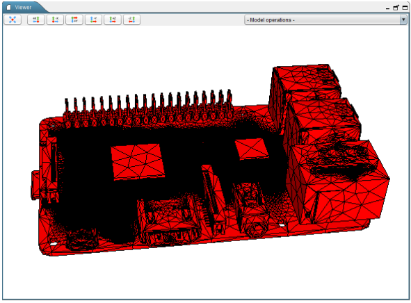
|
Please note that the imported tessellated surface must imperatively be a closed surface. EDGE displays a warning message to the user if it is not the case. Geometries imported from B-Rep models with the menu:File[Import > Tessellated geometry] menu or with the btn:[Tessellated geometry] option inside the "Add new shape" dialog are imported as a unique tessellated element. To separate elements and have more controls on the import, see advanced import options of the DeCADe additional plugin. |
GDML file
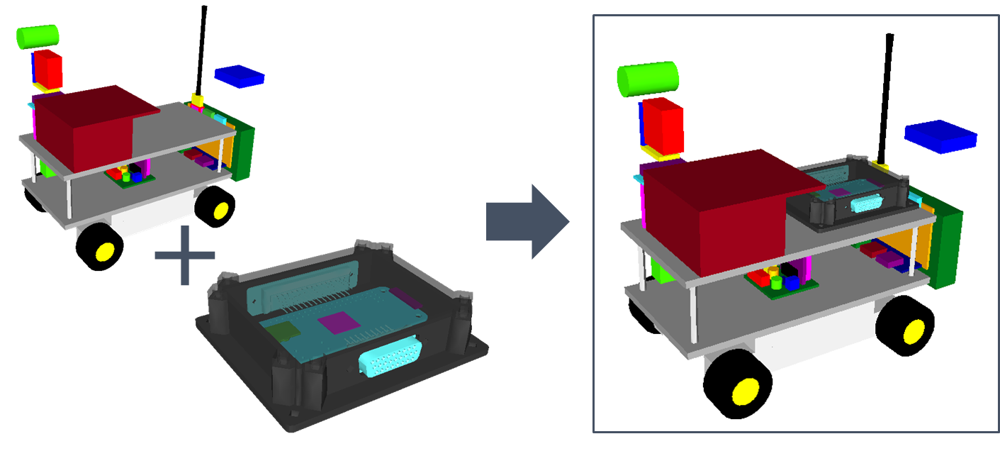
EDGE also allows importing all the geometry concepts from another GDML file and including them as a child of the currently selected element. This option can be very useful if users want to check the position of a specific subsystem (defined in the imported GDML file) in the whole system (main GDML file).
It is possible to import a sub-GDML file with the menu:File[Import > GDML File] menu or with the btn:[GDML File] option inside the "Add new shape" dialog.
Geometry edition
Creating and adding a new shape
The user has first to create a “world” shape that will include all subsequent shapes.
The position (0, 0, 0) corresponds to the barycentre of this world shape. Once this is done, it is possible to start the construction of the desired object.
|
Note about the "World" elemnt
Even if technically GDML allows creating a world smaller than the final object, it is not recommended. The world shape typically corresponds to the computational domain of numerous of simulation kernels using GDML files in input. Most of these tools will not work properly nor give relevant results if the world shape does not encapsulate all other elements. The relevant definition of the world shape remains on the responsibility of the user and with respect to the final targeted application. |
Clicking on the  button opens the New Shape Wizard.
On the left panel of the dialog box, all the available shapes are represented. A click on a shape selects it and shows its properties on the right panel. Properties requirement varies with the different shapes, but for each one the Name, Unit Configuration, Position and Rotation can be filled-up. All the properties can also be edited via the Properties panel.
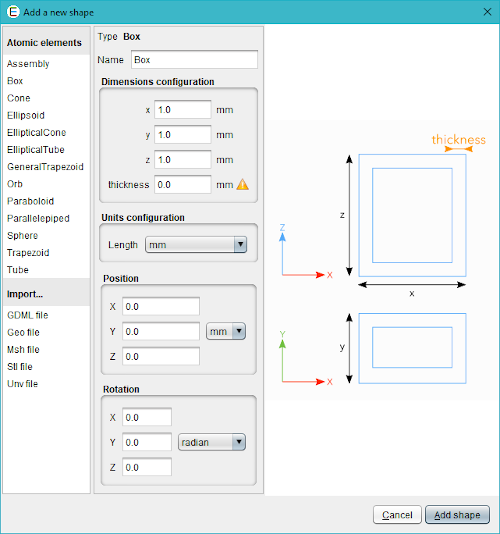
If the tree is empty, the first new shape will become the world shape. After that, each new shape will be added to the tree as a child of the current selected element. If no element is selected, the new element will be added as a child of the world shape. This feature makes possible the creation of objects with a complex hierarchy of objects.
The new shape dialog box displays all the available import options which may vary depending on the installed plugins. Basic ones are the B-Rep format files import (.geo, .msh, .stl, .unv), or the GDML file import.
Creating Boolean operation
Using the create Boolean operation button  , it is possible to create Union, Intersection and Subtraction directly in EDGE.
In order to create a Boolean operation, it is necessary to select two elements and click on the button. The dialog shown below will appear and let you choose a name for the Boolean operation, which element is the first and which one is the second and finally the type of operation.
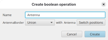
| The order of the two shapes in the operation is important for subtraction and intersection only. |
It is also possible to create directly a multi-union that groups more than two elements directly by selecting three or more shapes and clicking on the create Boolean operation button. In this case, only the name of the multi-union to create will be asked.
|
Currently, the multi-union construct in EDGE is a shortcut to create a succession of Boolean unions. It does not use the GDML Then when deconstructing a multi-union, the other unions of the construct are still present and should be deconstructed one after the other. |